
Home defense is a top priority for any prepper.
What good is preparing for a SHTF situation if all of your preps can easily be taken away?
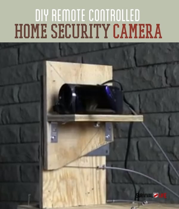
In need of an awesome home security system? We wanted one, too. The cost of a remote control security system is outrageous, so we decided to build our own.
Build this DIY remote controlled security camera, and nothing can happen in or around your home without you being able to see it.
This cool setup uses a basic video camera, one you can pick up inexpensively. Then, you just need wood and bike cables to make a pulley system that allows you top operate this amazing camera system from afar.
Check out the remote control camera video:
Read on and find out how to create a remote controlled camera of your own.
Also check out this remote control gun we attach to our remote camera system. Video and instructions coming soon, so be sure to check back.
Follow us on Facebook to be the first to know when we tell you all about it.

How to Build A Remote Control Video Camera:
Printable Instructions and drawings:
Tools Needed:
Phillips screwdriver and cordless drill with Phillips tip if available
Pliers
Braided steel cable cutters, small pair
Flat tip screwdriver
Saw to cut wood
Drill
1/16” drill bit
Parts Needed:
2@ 6”x6” lazy susans
4 @ 1-1/2”x1-1/2” angle brackets
1 box of #10 x1/2” pan head screws
1 pack of #10 x3/4” pan head screws
1 pack of #10 x 1-1/4” pan head screws
1 pack #10 flat washers
1@ 1/4-20 x 1” hex bolt for camera tiedown
16 @ #214 x 13/16 small screw eyes
8 @ #212 x 15/16 medium screw eyes
4 @ bicycle brake cable housings cut to the same length of 20’ (Can be up to 50’ pieces)
4 @ pieces of 1/16” braided steel cable cut to the same length of 22’ (Can be up to 52’ pieces)
8@ cable stop clamps (usually found at auto parts stores also called drum clamps and carburetor cable stops)
Small video camera with output cables for connection to TV or video monitor
Video extension cables and connectors roughly as long as the length you chose for your control cables
TV or video monitor
Build the Control Base with Pan Function
Step 1:
Mount 1 Lazy Susan to the bottom side of the pan base board using the pre drilled holes and 4 #10×1/2 inch screws.

Step 2:
Flip the pan base board over and attach 2 of the 1-1/2”x1-1/2” angle brackets using the pre drilled holes and 4 #10×1/2inch screws. These will support the upright tilt function support board.

Step 3:
Attach upright tilt function support board using the pre drilled holes and 4 #10×1/2inch screws.


Step 4:
Attach the bottom portion of the Lazy Susan to the main motion control base board using the pre drilled holes and 4 #10×1/2 inch screws.

Building the Control Base | Tilt Functions
Step 1:
Mount 1 Lazy Susan to the back side of the vertical tilt control board using the pre drilled holes and 3 #10×1/2 inch screws.

Step 2:
Take the camera base board and attach 2 of the 1-1/2”x1-1/2” angle brackets using the pre drilled holes and 4 #10×1/2inch screws. These will support the camera base board to the vertical tilt control board.

Step 3:
Flip the vertical tilt control board over and attach the camera base board using the pre drilled holes and 4 #10×1/2inch screws.

Step 4:
Attach bottom side of Lazy Susan to the upright tilt function support board using the pre drilled holes and 4 #10×1/2 inch screws.

Mount Eye Screws for Control Cables
Step 1:
Mount motion base cable standoff board to the main motion control base board using the pre drilled holes and 3 #10×3/4” screws.

Step 2:
Attach 3 screw eyes, 2 #214x 13/16 small screw eyes and 1 #212x 15/16 medium screw eye for each cable.
For the pan control cables, the medium screw eye will go to the back of motion base cable standoff board to support the cable housing, and a small screw eye in front of it to act as a cable housing stop. The remaining small screw will be used to attach the ends of the cables to the pan base board.

Step 3:
For the tilt control cables, the medium screw eyes and the center back edge of will go to the top edge back pre drilled hole of the upright tilt function support board, and the center back edge of upright tilt function support board to support the cable housing, and a small screw eye in front of it to act as a cable housing stop. The remaining small screw will be used to attach the ends of the cables to the vertical tilt control board.
Attach Cable Housings and Cables
Step 1:
Make sure all openings of the cut cable housing ends are open using the tip of a small Phillips tip screwdriver.

Step 2:
Being careful not to fray the ends of or kink the cables, fish each of the cables through a corresponding row of screw eyes, starting from the front of the device leading towards the back and then feeding through the cable housing. Do this for each of the cables.

Step 3:
Make sure each of the tilt and pan positions of the motion base are in their center positions, and that all the cables are pulled taught, and then minimally trim the ends of all the cables to the same length.


Assemble the Control Board
Step 1:
Attach the bottom cable standoff board to the base control board using 2 #10×3/4 inch screws from the bottom side of the base control board.

Step 2:
Attach top cable standoff board using 2 #10×1-1/4” screws from the top down.

Step 3:
Place screw eyes into cable standoff board, 4 small eyes to the back side of the standoff board for cable stops and 4 medium eyes to the front side of the standoff board in the appropriate pre drilled holes. Screw them down as close as possible to the top of the standoff board and that the eyes are lined up.

Step 4:
Mount standoffs for the control levers to the main control board.

Step 5:
Use the pre drilled holes and 4 #10×3/4screws inserted from the underside of the main control board to hold the standoffs down.

Step 6:
Mount the control levers to the control lever standoffs using 1 #10x 1-1/4” screw and 2 #10 flat washers between them for each control lever. Tighten till snug, then back off a half of a turn.

Step 7:
Place 2 of the small eye screws, one on each side of each of the control lever levers. Tighten them down as close as possible to the surface of the wood.

Step 8:
Attach Cables to the control lever. Run the cables in pairs, one control lever for the tilt function and one control lever for the pan function. Make sure that each of these positions are centered.

Step 9:
Use your cable stops to hold the cable ends in place, making sure that both your cables are tight and that there is not any slop in the motion to controller response.


Mount Camera to Control Base
Step 1:
Attach camera to base using the 1/4-20 hex bolt.

Step 2:
Attach cables to TV or video monitor.

Step 3:
Turn on TV and turn on home security camera, adjust all settings required for the two of them to talk to each other correctly. Test setup for correct operation, make adjustments where necessary.

Video Instructions:
Printable Instructions: PDF
Check back next week and learn how we turn this remote controlled home security camera into a REMOTE CONTROLLED GUN!

Like us on Facebook and subscribe to our newsletter to be the first to see this awesome DIY!
Like DIY weapons? Check out these articles:
- 7 Badass Weapons You Can Make At Home
- 7 REALLY Badass Weapons You Can Make At Home
- DIY Weapons To Awaken Your Inner Caveman
Like this post?Be sure to like us on Facebook (button below) so you can be the first to know about latest survival tips and off the grid living skills.
For awesome survival gear you can’t make at home, check out the Survival Life Store!
Follow us on Facebook, Instagram, Twitter, Pinterest, and Tumblr!
**Disclaimer: All content on this site is for informational purposes only. Please read our full disclaimer .**
Editor’s Note: This post was originally published on April 24, 2014, and has been updated for quality and relevancy.